
Jindal Composite Pipeline
Jindal Multi Layer Composite Pipeline
")
Jindal Tubes: Pioneering Force in the Pipe Manufacturing Industry
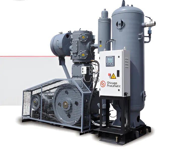
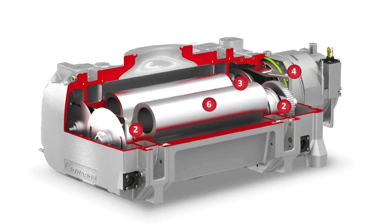
AirConnect is an innovative piping system for compressed air and inert gas distribution that uniquely combines all the benefits of both plastic and metal in a single pipe. The pipes and fittings are joined using a compression technique, eliminating the need for welding, gluing, fusing, or threading.
AirConnect – Advanced Aluminium Composite Piping System
AirConnect pipes are constructed with an inner and outer layer of polyethylene, sandwiching an aluminium core in between. All the layers are permanently bonded together using an intermediate layer of polyethylene-based adhesive. The aluminium core is sealed using overlap welding technology, which enables the pipe to withstand high working pressures.
")


Technical Specification
Raw Material - POLYETHYLENE
Polyethylene (PE) is a polymer consisting of long chains of the monomer ethylene. It is created through the polymerization of ethene and is classified into different types based on density. High-Density Polyethylene (HDPE) is used to manufacture AirConnect Pipes. It has a low degree of branching and thus stronger intermolecular forces and tensile strength.
The HDPE used in AirConnect Pipes is food-grade, and hence, hygienic.

")
")
Piping System Design
Raw Material - POLYETHYLENE
- Locate each process, workstation, or piece of equipment that uses compressed air. They should be positioned on a layout plan, and a complete list should be prepared to simplify record-keeping. This initial step will serve as the foundation for your piping layout.
- Determine the volume of air and required pressure range at each location. Flow and pressure data can typically be obtained from the equipment manufacturer. If such values are not available, use estimated figures until actual values are provided.
- Define system conditioning requirements for each equipment unit. This includes permissible levels of moisture content, particulate matter, and oil. You may need air treatment components like dryers, filters, lubricators, and pressure regulators.
Calculate the actual usage time of each tool or process per minute. This is called the duty cycle. In most industrial setups, similar tools and processes are grouped together for efficiency.
")
- Identify the maximum number of simultaneous users across all lines and the entire project. This is known as the use factor, and it helps in accurately sizing the system.
- Determine the allowable leakage in the system. Leakage can result from the number of joints, type of fittings, and the initial quality of assembly. More components typically mean more leakage. A well-maintained system usually exhibits 2–5% allowable leakage.
- Establish any allowance for future expansion. Thought should be given to over sizing some components (i.e., main supply lines) to avoid the cost of replacement
at a later date. Select the air compressor layout and assign a preliminary pressure drop for the system.
- Select the air compressor type, conditioning equipment, equipment location, and air inlet, making sure that scfm (L/min) is used consistently for both the system and compressor capacity rating.
- Note: This allowable leakage rate applies only to compressed air made on site. All other inert gas systems must be designed with the strictest health and safety considerations in mind including preventing leakage of any pipe contents.
TO START, THE FOLLOWING INFORMATION MUST BE AVAILABLE:
Total connected flow rate cfm (L/min) of all air-using devices, including flow to the air dryer system, if Applicable.
Maximum pressure (psi) of all air using devices.
Duty cycle and use factors for these devices giving maximum expected use of air.
Leakage and future expansion allowance, cfm (L/min).
Allowable pressure drops for the entire system, including piping and conditioning equipment.
Altitude, temperature, and contaminant removal corrections.
Location where adequate space is available for air compressor and all ancillary equipment.
Produce a final piping layout and size the piping Network.
Feature Comparision
| FEATURE | AIR-Connect | Aluminium Pipes | PPR-C Pipes |
|---|---|---|---|
| COST | Most cost-effective. Low initial investment, long Working life and no maintenance. | Most expensive | Least Expensive but has a short Working Life |
| HYGIENE | Hygienic, made from 100% Food Grade Polyethylene. | Hygienic | Not hygienic, is not made from Food grade material. |
| FLOW RATE | Best, has smooth inner surface and minimum use of fittings. | Good, has smooth inner surface but use of more fittings (elbows and couplers) | Good, has smooth inner surface but use of more fittings (elbows and couplers) |
| CORROSION RESISTANCE | Good | Good | Good |
| BENDABILITY | Bendable without any spring back | Not bendable | Not bendable |
| REQUIREMENT OF FITTINGS | Minimum, use of Elbows and Couplers is eliminated | High, fittings are required at bends and joints at every 6 mts | High, fittings are required at bends and joints at every 6 mts |
| JOINING METHOD | Compression method, Leak proof, fittings can be re-opened for maintenance work | Push-in method | Electric fusion method, results in a permanent joint and cannot be re-opened for maintenance work. |
| WEIGHT | Light-weight, Upto 90% lighter than GI pipes. | Heavy, 5 times heavier than Air Connect Pipes | Heavy, compared to Air Connect Pipes |
| STORAGE, HANDLING & TRANSPORTATION | Easy, are light weight and packed in coils of upto 200 mts. Come in Carton packing. | Difficult, are heavy and packed in lengths of 6 mts | Difficult, are heavy and packed in lengths of 6 mts |
| INSTALLATION | Fast and Easy. Requires basic Tools only. | Fast and Easy. Requires basic Tools only. | Time consuming, requires electricity and Heating machine |
| LINEAR THERMAL EXPANSION | Low | Low | Low |
| WASTAGES | Zero wastage | High | High |
")
Raw Material – ALUMINIUM
Aluminium is a soft, lightweight, non-toxic, and malleable metal, with an appearance ranging from silvery to dull gray depending on the surface roughness. Aluminium alloys have yield strengths ranging from 200 MPa to 600 MPa. For Air Connect pipes, a specialized grade of aluminium is used, which is manufactured specifically for these pipes. This material is engineered to provide the right balance of strength and flexibility as required for compressed air applications.
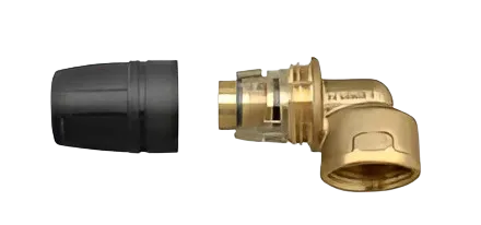
JINDALEZ- FIT COMPRESSION FITTINGS
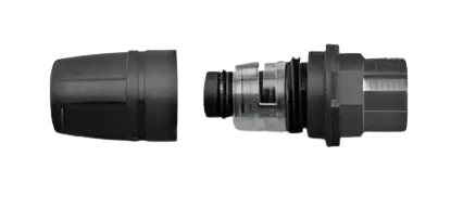
EZ-Fit Compression Fittings
EZ-Fit fittings combine the positive features of high reliability with a simple installation technique that does not require any special tools. A permanent pipe joint is achieved by compression, i.e., tightening the nut against the tapered split ring. The profiles of the two pieces are designed to cause a progressive shrinkage of the split ring and to distribute the compression forces evenly across the contact surface. A specially designed seal housing is equipped with a slip-proof profile called O-Rings, which come into direct contact with the pipe to ensure a leak-proof and secure connection.
")
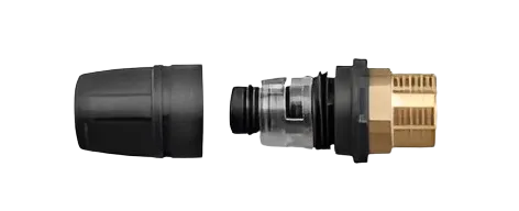
EZ-Fit Fittings – Material & Advantages
EZ-Fit fittings are made from high-quality engineering nylon using advanced injection molding technology, which makes them extremely reliable and resistant to leakages. The fittings are both rigid and lightweight at the same time. This system’s simplicity and economics are based on the use of standard tools like spanners and standardized threads, which make it possible to connect easily with any system.
")
")
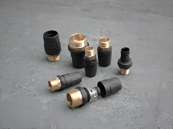
EZ-Fit Fittings Come in 3 Categories as Listed Below:
EZ-FIT
Full Plastic component
Developed with advanced injection moulding
Lightweight & Economical
Removable and Reusable
Quick and simple installation
EZ-Hybrid
Hybrid Technology
Strength of Brass combined with the cost effectiveness of plastic
Removable and Reusable
Quick and simple installation
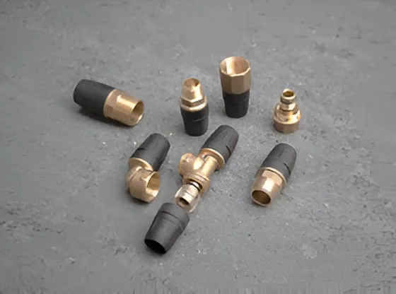
EZ-FIT
Full Brass Body
Plastic Compression Nut and Split ring
Superior Strength
Removable and Reusable
Quick and simple installation
Determining Pressure Loss in Jindal MLC Pipe
- To use pressure drop charts, it is necessary to find the equivalent length of run from the compressor to the farthest point in the step. In addition to the actual measured pipe length, the effect of fittings must be considered. This is because fittings create an obstruction to the flow of air. This degree of obstruction has been converted to an equivalent length of pipe in order to make calculations easy.
- Determine the actual pressure drop that will occur only in the piping system. Since the air compressor has not been selected yet, this figure is variable. A smaller pipe size may lead to higher compressor horsepower. It is considered good practice to oversize distribution mains to allow for future growth and the addition of condition equipment that may add a pressure drop not anticipated at the time of original design. It should be noted that this practice may result in a higher initial cost for the piping system.
")
- Size the piping using the appropriate charts, having first calculated the flow rate at the operating pressure and operating temperature, scfm, and the allowable friction loss in each section of the piping being sized. Since all pipe sizing charts are calculated using loss of pressure per some length of piping (100 ft {30.5m}), it is necessary to arrive at the required value for the chart you are using.

EZ-Fit Compression Fittings
Nylon is one of the most widely used plastics because of its extreme strength, wear resistance, and self-lubricating properties. Nylons are also known to have high impact resistance, high operating temperature and are lightweight. Nylon is commonly used as a replacement for bronze, brass, aluminum, steel and other metals. The glass reinforcement gives the material higher compressive strength and rigidity, as well as improved frictional characteristics.
")
Contaminants
There are four general classes of contamination:
Liquids | Vapor | Gas | Particulates
An understanding of the various pollutants in the air is helpful when an engineer has to decide what equipment is required to effectively reduce or remove them. The required level of protection from the various contaminants depends upon the purpose for the air. Prior to the selection of equipment the performance criteria for each system, along with the identity and quantity of pollutants, must be determined.

Determining Pressure Loss Using Equation
As air flows through the Air Connect piping system, it will experience friction resistance between the air and the pipe wall resulting in a pressure loss.
The pressure drops in the Air Connect pipe can be determined using the following equation:
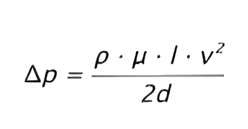
Where:
d= Internal Diameter of Pipe (in Mtr)l= Pipe Length (in Mtr)v= Air Velocity (Mtr/Sec)p= Pressure Loss (Pa)μ= Coefficient of friction
Pressure Loss Through Fittings in Equivalent Feet
| SPECIFICATION (mm) | FITTING TYPE | VELOCITY (fps) 200psi @ 23°C | |||||
|---|---|---|---|---|---|---|---|
| 5 | 10 | 15 | 20 | 30 | 40 | ||
| 1216 | Straight | 1 | 2 | 2 | 2 | 3 | 3 |
| 1216 | Tee Branch, Elbow | 4 | 5 | 5 | 6 | 6 | 6 |
| 1620 | Straight | 2 | 3 | 4 | 4 | 4 | 4 |
| 1620 | Tee Branch, Elbow | 6 | 7 | 8 | 8 | 9 | 9 |
| 2025 | Straight | 4 | 4 | 5 | 5 | 5 | 6 |
| 2025 | Tee Branch, Elbow | 7 | 8 | 9 | 10 | 10 | 10 |
Additional Cost Incurred Due To Compressed Air Leakage
| LEAKAGE SIZE (mm) | ENERGY LOSS (kw) | COST OF AIR LEAKAGE (Rs/annum) |
|---|---|---|
| 0.8 | 0.2 | 9,000 |
| 1.6 | 0.8 | 36,000 |
| 3.2 | 3.0 | 1,35,000 |
| 6.4 | 12 | 5,40,000 |